 |
|
 |
| |

Dear Readers,
This is the second of a series of quarterly reviews on selected topics of electrical/electronic connector
technology. You are invited to suggest a review topic of interest.
Roland S. Timsit, President
Timron Scientific Consulting Inc.
Tel: 416-787-8161,
www.timron-inc.com
|
 |

The Temperature of an Electrically Heated Contact Spot
In designing reliable electronic and electrical connectors, it is essential that a minimum
specification on contact resistance be met. One of the drivers for this specification is the
requirement that contact temperature does not exceed a maximum value
under the worst-case electrical loading condition. An unacceptably elevated contact temperature
leads to accelerated connector degradation. This degradation stems from the action of mechanisms
such as loss of mechanical contact load due to stress relaxation and metal flow, oxidation,
interdiffusion and intermetallics formation etc [1,2]. In this newsletter, we review the contact
parameters that determine contact temperature during passage of an electrical current.
Contact Resistance and Contact temperature
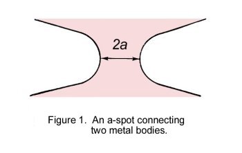 The electrical resistance of two bodies of electrical resistivity ρ joined by a
circular constriction of radius a, as shown in Fig.1, is given as ρ/2a [1,3]. If a DC electrical current I passing through the contact spot (also known as a-spot [3])
does not heat the a-spot significantly, the voltage drop across the constriction is simply given
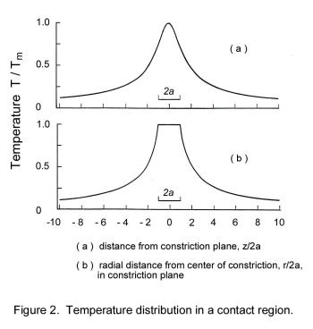
as ρI/2a. Under conditions where significant joule heat is produced within the constriction,
the crowding of current lines within the a-spot generates a thermal gradient in the vicinity of
that constriction. The steady-state thermal gradient produced by joule heating of a circular a-spot linking two identical metallic
bodies is shown schematically in Fig. 2 [4]. The maximum temperature Tm occurs in the plane of the
constriction. The effect of the temperature gradient complicates the relationship between
voltage-drop across the contact, the electrical current and the a-spot dimension. We now
examine the nature of this relationship.
The electrical resistance of two bodies of electrical resistivity ρ joined by a
circular constriction of radius a, as shown in Fig.1, is given as ρ/2a [1,3]. If a DC electrical current I passing through the contact spot (also known as a-spot [3])
does not heat the a-spot significantly, the voltage drop across the constriction is simply given
as ρI/2a. Under conditions where significant joule heat is produced within the constriction,
the crowding of current lines within the a-spot generates a thermal gradient in the vicinity of
that constriction. The steady-state thermal gradient produced by joule heating of a circular a-spot linking two identical metallic
bodies is shown schematically in Fig. 2 [4]. The maximum temperature Tm occurs in the plane of the
constriction. The effect of the temperature gradient complicates the relationship between
voltage-drop across the contact, the electrical current and the a-spot dimension. We now
examine the nature of this relationship.
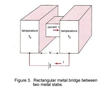
 The simplest way of understanding the relationship of contact temperature and joule heating in the
contact region is to consider the steady-state temperature produced within an electrically conductive
bridge connecting two metal slabs. This is illustrated in Fig.3. We assume that the length of the
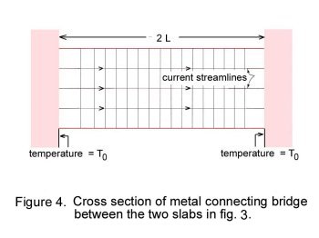
conducting bridge is 2L and the rectangular cross section is A. We also assume that the temperature
of the two metals slabs is uniform and given as To. An electrical current of uniform density j is
passed through the bridge, also as shown in Fig. 4. If all conductors are thermally insulated from
the surroundings, the differential equation governing the temperature distribution T(x) along the
metal bridge is [5]
The simplest way of understanding the relationship of contact temperature and joule heating in the
contact region is to consider the steady-state temperature produced within an electrically conductive
bridge connecting two metal slabs. This is illustrated in Fig.3. We assume that the length of the
conducting bridge is 2L and the rectangular cross section is A. We also assume that the temperature
of the two metals slabs is uniform and given as To. An electrical current of uniform density j is
passed through the bridge, also as shown in Fig. 4. If all conductors are thermally insulated from
the surroundings, the differential equation governing the temperature distribution T(x) along the
metal bridge is [5]
where λ and ρ are the thermal conductivity and electrical resistivity of the conductor
material respectively, and x is the distance along the conductor with x=0 taken at the center of the bridge. Equation (1) states that the joule
heat ρj2 generated per unit volume within the connecting bridge is dissipated
by thermal conduction in the metal. If for simplicity λ and ρ are assumed temperature
independent, the solution of Eq. (1) is straightforward and is given as
| T(x) = To + (ρ/λ) j2 ( L2 - x2 ). |
(2) |
Note that the temperature distribution within the conductor is parabolic with the maximum T(0) occurring
at the center x = 0 of the conductor. The minimum temperature To occurs at x = L and x = - L.
We shall designate the maximum temperature T(0) as Tm.
Since λ and ρ are assumed to be temperature independent, the voltage drop across the bar is given as
where j is the current density given as I/A. The difference between the maximum temperature in
the bridge and the temperature To at the ends i.e. the Supertemperature, is given as
Note the following important points in Eq.(3), also known as the Voltage-Temperature relation:
- the Supertemperature [ Tm - To ] is determined by the voltage-drop across the metal bridge,
- although the temperature distribution within the connecting bridge depends on the bridge geometry as
indicated in Eq.(2), the Supertemperature described by Eq.(3) does not depend explicitly on contact geometry,
- Eq.(3) is valid only where heat is dissipated from the conductor only by conduction to the ends of the
conductor and to the two metal slabs held at the temperature To. No heat is lost to the surrounding
environment (i.e. air) from the conductor sides since the conductor is thermally insulated.
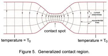
The absence of dependence of the Supertemperature on conductor geometry indicates that the relationship expressed by
Eq. (3) holds for an electrical junction of any shape including the shape shown in Fig. 5. In that junction,
the temperature distribution follows the pattern illustrated in Fig. 2 and drops to the value To of the bulk contacting
bodies within a short distance from the constriction. Again, we remind the reader that the temperature distribution
within the junction in Fig.5 is not parabolic as indicated in Eq.(2), since the temperature distribution depends on
contact geometry. Only the Supertemperature [ Tm - To ] is independent of contact geometry.
The Voltage-Temperature (V-T) relation expressed in Eq.(3) is a special case of the general relation between voltage and maximum
temperature [3,4] in a thermally insulated body carrying an electrical current, given as
 |
(4) |
 In the above expression, the parameters λ and ρ may be temperature dependent. It may be easily verified
that Eq.(4) reduces to Eq.(3) where λ and ρ are constant (i.e. do not vary with temperature). The general
V-T relation expressed by Eq.(4) identifies the voltage-drop across a contact, not the electrical current,
as the fundamental parameter for contact temperature.
In the above expression, the parameters λ and ρ may be temperature dependent. It may be easily verified
that Eq.(4) reduces to Eq.(3) where λ and ρ are constant (i.e. do not vary with temperature). The general
V-T relation expressed by Eq.(4) identifies the voltage-drop across a contact, not the electrical current,
as the fundamental parameter for contact temperature.
The Wiedemann-Franz Law
For many connector materials, there is relationship linking the electrical resistivity ρ and the thermal
conductivity λ. This relationship is known as the Wiedemann-Franz law and states that the product λρ
depends only the absolute temperature, as
where L is the Lorenz constant (2.45 x 10⁻⁸ (V/K)2) and T is the absolute temperature (in kelvin).
Although this relation provides a reasonable description of thermal and electrical transport properties in metals over
the temperature range generally relevant to ordinary electrical contacts, it is not universally valid. The origin
of the Wiedemann-Franz law is discussed in reference [1]. If the relation (5) holds, then Eq.(4) immediately yields
the rigorously valid V-T relation as
| V2 = 4L ( Tm2 - To2 ) |
(6) |
which is independent of contact geometry and of the materials in contact. It may easily be shown that Eq.(6) reduces to Eq.(3)
when the thermal conductivity and the electrical resistivity are independent of temperature [1]. The dependence of the maximum contact temperature
Tm on the voltage V across a constriction is shown in Fig. 6. The contact temperatures were evaluated from Eq.(6)
for a bulk temperature To of 20oC and 100oC. Note that a voltage-drop of 0.3 to 0.4 volt leads to contact
temperatures that exceed the melting point of most electrical contact materials. The "softening" and "melting" voltages
for several contact materials are listed in Table 1.
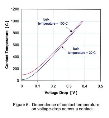
Table 1
Voltage for Softening (Vs) and Melting (Vm)
of Common Electrical Contact Materials
Material |
Vs
Softening
(V) |
Vm
Melting
(V) |
Al
Fe
Ni
Cu
Zn
Mo
Ag
Cd
Sn
Au
W
Pt
Pd
Pb
60Cu-40Zn
60Cu-40Sn
Stainless Steel
WC, Co |
0.1
0.19
0.16
0.12
0.1
0.25
0.09
0.07
0.08
0.4
0.25
0.12
0.27
0.6 |
0.3
0.19
0.16
0.43
0.17
0.75
0.37
0.15
0.13
0.43
1.1
0.65
0.57
0.19
0.2
0.15
0.55 |
Thermal Risetime of an Electrically Heated Contact Spot
The above discussion addressed the V-T relation in contacts heated by a DC current where a thermal
steady state condition had been reached. What happens when the electrical is alternating and contact heating
varies with time? Fortunately, the description of contact temperature in terms of voltage-drop remains simple.
It has been shown [1,3] that the time constant that characterizes temperature rise in the neighbourhood of a circular
constriction of radius a, due to joule heating, is ca2/4λ where c is the heat capacity
and λ is the thermal conductivity . For electrical conductors such as copper, λ and c take
values of 400 W m-1 oC-1 and 3.44x10⁶ J m-3 respectively. The time
constant is thus 2.2x10⁻⁷ second for a constriction of radius of 10 μm in a copper-copper interface.
The small risetime associated with the heating of an a-spot forms the basis on which thermal transients are
usually ignored in dealing with stationary or slowly moving contacts. In these applications, only the equilibrium
contact temperature is of interest. Thermal transients are taken into account only in applications of rapidly moving
contacts such as brush contacts, or in high frequency/high-power electrical connections.
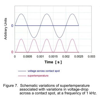 Due to the small thermal risetime associated with a-spot heating, the contact temperature follows voltage variations
across a contact almost instantaneously, so long as the frequency of the applied voltage does not exceed about 100 kHz.
Figure 7 shows schematically the variations in contact temperature associated with sinusoidal variations in voltage-drop across
the contact at a frequency of 1 kHz, when the temperature swing is not excessive. Note that temperature variations are also
sinusoidal and occur at a frequency of 2 kHz. This doubling of temperature fluctuation frequency stems from the dependence
of a-spot temperature on the square of the voltage V. The temperature fluctuations will be distorted from purely
sinusoidal when the maximum temperature approaches the softening point of the contact materials.
Due to the small thermal risetime associated with a-spot heating, the contact temperature follows voltage variations
across a contact almost instantaneously, so long as the frequency of the applied voltage does not exceed about 100 kHz.
Figure 7 shows schematically the variations in contact temperature associated with sinusoidal variations in voltage-drop across
the contact at a frequency of 1 kHz, when the temperature swing is not excessive. Note that temperature variations are also
sinusoidal and occur at a frequency of 2 kHz. This doubling of temperature fluctuation frequency stems from the dependence
of a-spot temperature on the square of the voltage V. The temperature fluctuations will be distorted from purely
sinusoidal when the maximum temperature approaches the softening point of the contact materials.
Summary
The parameter that relates directly to the temperature in an a-spot is the voltage-drop across the
contact, not the current. Temperature variations due to alternating voltage across the contact occur at twice the
frequency of the applied voltage.
References
- Timsit, R.S., "Electrical Contact Resistance: Fundamental Principles", in Electrical Contacts, Principles and Applications, Ed. Slade, P.G., p. 1, Marcel Dekker, Inc., New York, 1999.
- Mroczkowski, R.S., Electric Connector Handbook, McGraw-Hill, New York, 1998.
- Holm, R., Electric Contacts, Theory and Applications, Springer-Verlag, Berlin, 1976.
- Greenwood, J.A. and Williamson, J.B.P., "Electrical Conduction in Solids, II. Theory of Temperature-Dependent Conductors," Proc. Roy. Soc., A246, p. 13 1958.
- Carlslaw, H.S. and Jaeger, J.C., Conduction of Heat in Solids, Oxford University Press, London, 1959.
|
|
|
 |
|
 |
|